Category Archives: Real-time Graphics

Close to deferring the deferred demo post…

Yeah, I was quite close to postpone the writing of this post to tomorrow, but I won’t. πŸ™‚
The title is humorous but clear, my last demo deals again with deferred shading.

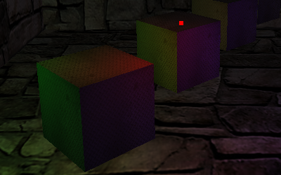
GLSL_deferred with SSAO, iterative parallax mapping and Depth of Field

This time I made every effort to do things right: there is support for directional, point and spot lights and, much more important for performances, lights are rendered only inside their influence volumes using projective texturing.
This means that while directional ones affect everything and have to be rendered as full screen quads, point lights are only rendered as cubes and spot lights as pyramids.

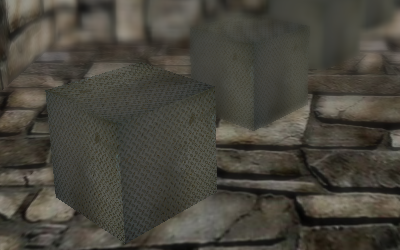
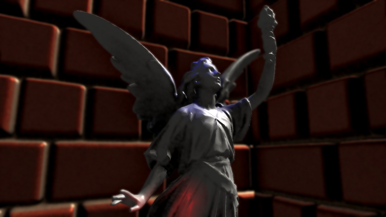
Comparison between disabled and enabled SSAO

This is slightly different from the usual approach taken, which uses spheres and cones but is also a bit more vertex heavy. πŸ™‚
Rendering bounding shapes should barely affect performance, but makes the check for camera position a bit different.
The check is disabled by default as it is sufficient to cull front faces and invert the depth test to avoid double lighting issue and benefit from some depth optimization.
By enabling the check the application will expose my poor approximation of checking if the camera is inside a pyramid by using a formula meant for a cone, so better if it stays disabled, while the volume is not intersecting the far plane everything should behave as expected… πŸ˜€

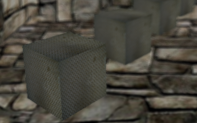
Comparison between normal mapping and iterative parallax mapping

The demo is also a bigger attempt into effects integrations, it will serve as a test bed for a more organized and high level framework.
As a matter of fact it also features Screen Space Ambient Occlusion, Iterative Parallax Mapping and Depth of Field.
Very cool stuff, but I already have a list of things that I would like to implement sooner or later, like a Light Pre-Pass, a couple of advanced shadow mapping techniques, the integration of water rendering, HDR illumination and the reconstruction of position from depth.

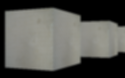
Normal rendering and Depth of Field blur

I have published the sources and a video (Vimeo | YouTube), that for the first time comes with a nice soundtrack: it’s Nova Siberia by Big Giant Circles (Jimmy Hinson) from OverClocked ReMix! πŸ˜‰

Note: I have had a hard time with glc, x264, mencoder and ffmpeg but still YouTube doesn’t accept my video together with the sound, at the moment I have uploaded a mute version.

Gimme some (real-time) water!

Computer generated water has always interested me, since the days of POVRay on Amiga I was trying to simulate it in some way.
Some days ago, while studying another technique, I put everything aside because in that particular moment I felt the urge to implement a water shader. πŸ˜€

water_crop

I began looking for existing implementations and I found Reimer’s XNA tutorial, a simple approach which I think could be optimized, but that already provides a nice looking water.

The technique is composed of four passes:

  • Rendering the reflection map
  • Rendering the refraction map
  • Rendering the scene
  • Rendering the water plane linearly interpolating the two maps with a Fresnel term

One of the drawbacks is represented by the fact that the whole scene is rendered three times during the first three passes, I’m sure that this procedure could be optimized, but I was lazy enough to cease any further test. πŸ™‚
Moreover having every pass clearly separated helps with debugging and makes the application capable of displaying them one at a time.

The scene is rendered with parallax mapping enabled, and that is more evident than ever thanks to the new bricks textures, but with an altered shader that also performs user plane clipping, decisive for the first two passes.
Talking about the Fresnel term I have implemented a naive (nothing more than a dot(V, N)) and a better approximation based on the Nvidia’s Fresnel reflection paper.
In the source you will find both but only the first one is actually used, it works better in the scene used in this demo.
You can easily see that waves are fake, the water is composed of just two triangles, the ripple animation is generated by the fragment shader altering texture coordinates based on a normal map and using a time variable.

Of course you can have a look at videos on YouTube (GLSL_water, GLSL_water_HD) or Vimeo (GLSL_water, GLSL_water_HD) and download the sources.

High Dynamic Range galore

In January, during my internship activity, I was researching in the field of HDR imaging, today I had the time, at last, to polish a bit and release the two demos I made at the time.

They both load an RGBE image (the two you see here are courtesy of the Paul Devebec’s Light Probe Image Gallery) through the library of Bruce Walter.

Light probe at different exposure levels (hdr_load1)

Light probe at different exposure levels (hdr_load1)

The first demo implements the technique described in the article High Dynamic Range Rendering published on GameDev.net and is based on five passes and four FBOs:

  1. Rendering of the floating-point texture in an FBO
  2. Down-sampling in a 1/4 FBO and high-pass filter
  3. Gaussian filter along the X axis
  4. Gaussian filter along the Y axis
  5. Tone-mapping and composition

The algorithm is very simple, it first renders the original scene then it extracts bright parts at the second pass, which merely discards fragments which are below a specified threshold:

// excrpt from hipass.frag
if (colorMap.r > 1.0 || colorMap.g > 1.0 || colorMap.b > 1.0)
	gl_FragColor = colorMap;
else
	gl_FragColor = vec4(0.0);

While the third and fourth passes blurs the bright mask, the last one mixes it with the first FBO and sets exposure and gamma to achieve a bloom effect.

// excerpt from tonemap.frag
gl_FragColor = colorMap + Factor * (bloomMap - colorMap);
gl_FragColor *= Exposure;
gl_FragColor = pow(gl_FragColor, vec4(Gamma));
Light probe at different exposure levels (hdr_load2)

Light probe at different exposure levels (hdr_load2)

The second demo implements the technique described in the article High Dynamic Range Rendering in XNA published on Ziggyware and is based on seven passed and more than five FBOs:

  1. Rendering of the floating-point texture in an FBO
  2. Calculating maximum and mean luminance for the entire scene
  3. Bright-pass filter
  4. Gaussian filter along the X axis
  5. Gaussian filter along the Y axis
  6. Tone-mapping
  7. Bloom layer addition

This approach is far more complex than the previous one and is based on converting the scene to its luminance (defined as Y = 0.299*R + 0.587*G + 0.114*B) version, the mean and maximum value can be calculated using a particular downsampling shader and working in more passes, at each one rendering on an FBO with a smaller resolution than the previous until the last pass, when you render the luminance of the entire scene on a 1×1 FBO.

As usual you can have a look at YouTube (GLSL_hdrload1, GLSL_hdrload2) or Vimeo (GLSL_hdrload1, GLSL_hdrload2) videos and download the sources.

Yet another toon shader

Maybe is true, as I wrote in the README file, that I coded this demo because I felt like the only one who hasn’t yet implemented a toon shader. πŸ™‚
Actually this is not the only reason, I came with the inspiration when I was presenting the first part of my updated Modern GPUs slides at the university, this time the event was organized by some students and advertised with leaflets. πŸ˜‰
So, for the second part that will be held next Wednesday, I’m planning to integrate the explanations about the internals of this demo.

From untextured to textured with outlines

From untextured to textured with outlines

It was easy and fast to have a basic toon shader working, thanks to the Lighthouse 3D tutorial.
This version uses a cascade of if-then-else instead of a more usual 1D texture lookup but, judging from the tests I have run, it’s not a performance issue, at least on GeForce 8 and newer cards.

For the edge detecting I wanted to exploit the fragment shader capabilities, working in screen space with the sobel operator and thus being independent from geometric complexity.

The only problem was about *what* to filter.

  1. The first test was straight, I filtered the rendered image, a grey version of the textured and lit MrFixit head, but the results were poor: edge detecting outlined toon lighting shades too.
  2. In the second one I decided to filter the depth buffer, I could get rid of colour to grey conversion but, again, the results were not satisfactory: there were no outlines in the model, just a contour all around.
    Maybe it could have been corrected with a per-model clip planes tuning, but I gave up.
  3. With the third test I filtered out the unilluminated color texture and the results were better. Unfortunately it relied on the presence of a texture and outlined too much details.
  4. I think the fourth approach, as seen in this demo, is the best one.
    I used MRTs to save the eye-space normal buffer during the toon shader pass, then I filtered a grey version of it, outlining the contour plus some other geometric details.

A small note: saving an already grey converted buffer in the toon shader pass speeds up the demo a bit, but storing the normal in a single 8 bits component of the texture causes a loss of precision that leads to some visible artefacts.
Using a floating point texture helps with the precision issue but makes the demo too slow.
Maybe I should try using a single component texture or some kind of RGBA packing algorithm…

As usual you can have a look at YouTube or Vimeo videos and download the sources.

Habemus OpenGL 3.0!

We have been waiting OpenGL 3.0 for ages, we were all very excited about the wonderful features ARB was promising, then, on the 11th of August 2008, the specs were released…
I, like everyone else, was really disappointed, the Architecture Review Board was not only really late on schedule but it didn’t keep its word about many key features that should have been introduced with this release.
Nevertheless I’m still confident in the future, when older API functions will be removed and not simply, as in the current version, tagged as deprecated.

OpenGL3 Logo

Now, after the long but needed introduction, let’s talk about things that matter: today the ArchLinux team moved the new stable 180.22 driver release from the [testing] to the [extra] repository.
Well, apart from the equally important CUDA 2.1 and VDPAU support, this release has been bundled with OpenGL 3 and GLSL 1.30 support, so have a look at how to create an OpenGL 3.0 context.

First of all, it seems like there’s no other way to open the new context without getting your hands dirty, that is talking directly with GLX.
What follows is a snippet to create an OpenGL 3.0 context integrated in SDL 1.2, which still doesn’t support it natively.

First of all you need some new defines.

#define GLX_CONTEXT_DEBUG_BIT_ARB                         0x00000001
#define GLX_CONTEXT_FORWARD_COMPATIBLE_BIT_ARB   0x00000002
#define GLX_CONTEXT_MAJOR_VERSION_ARB                  0x2091
#define GLX_CONTEXT_MINOR_VERSION_ARB                   0x2092
#define GLX_CONTEXT_FLAGS_ARB                                0x2094

You need also to retrieve the address of the following new GLX function.

typedef GLXContext ( * PFNGLXCREATECONTEXTATTRIBSARBPROC) 
	(Display *dpy, GLXFBConfig config, GLXContext share_context, Bool direct, const int *attrib_list);
PFNGLXCREATECONTEXTATTRIBSARBPROC glXCreateContextAttribsARB = 
	(PFNGLXCREATECONTEXTATTRIBSARBPROC)glXGetProcAddress((GLubyte*)"glXCreateContextAttribsARB");

Then you have to define a bunch of GLX related variables.

Display *dpy;
GLXDrawable draw, read;
GLXContext ctx, ctx3;
GLXFBConfig *cfg;
int nelements;
int attribs[]= {
	GLX_CONTEXT_MAJOR_VERSION_ARB, 3,
	GLX_CONTEXT_MINOR_VERSION_ARB, 0,
	GLX_CONTEXT_FLAGS_ARB, GLX_CONTEXT_FORWARD_COMPATIBLE_BIT_ARB,
	0
};

At last, after having called SDL_SetVideoMode(), create a new context, make it current and destroy the old one.

ctx = glXGetCurrentContext();
dpy = glXGetCurrentDisplay();
draw = glXGetCurrentDrawable();
read = glXGetCurrentReadDrawable();
cfg = glXGetFBConfigs(dpy, 0, &nelements);
ctx3 = glXCreateContextAttribsARB(dpy, *cfg, 0, 1, attribs);
glXMakeContextCurrent(dpy, draw, read, ctx3);
glXDestroyContext(dpy, ctx);

Don’t forget to put some querying code, just to be sure the whole process worked. πŸ˜€

const GLubyte* string;

string = glGetString(GL_VENDOR);
printf("Vendor: %s\n", string);
string = glGetString(GL_RENDERER);
printf("Renderer: %s\n", string);
string = glGetString(GL_VERSION);
printf("OpenGL Version: %s\n", string);
string = glGetString(GL_SHADING_LANGUAGE_VERSION);
printf("GLSL Version: %s\n\n", string);

On my workstation I get this:
Vendor: NVIDIA Corporation
Renderer: GeForce 8600 GT/PCI/SSE2
OpenGL Version: 3.0 NVIDIA 180.22
GLSL Version: 1.30 NVIDIA via Cg compiler

If you want to retrieve also the extension list, a new function can help you simplify the process.

typedef const GLubyte * (APIENTRYP PFNGLGETSTRINGIPROC) (GLenum name, GLuint index);
PFNGLGETSTRINGIPROC glGetStringi = (PFNGLGETSTRINGIPROC)glXGetProcAddress((GLubyte*)"glGetStringi");

You can then use it like this:

GLint numExtensions = 0;
glGetIntegerv(GL_NUM_EXTENSIONS, &numExtensions);

printf(“Extension list: \n”);
for (int i = 0; i < numExtensions; ++i) { printf("%s ", glGetStringi(GL_EXTENSIONS, i)); } printf("\n"); [/sourcecode] This new OpenGL version seems to perform just like the old one at the moment, drivers do not honour the GLX_CONTEXT_FORWARD_COMPATIBLE_BIT_ARB attribute, this means everything is still in place, backward compatible and unoptimized. πŸ™

Blurring the parallax

Today I have published the first demo making use of my new C++ class library, I designed it to be very easily ported to a strict GL3 profile or to ES 2.0.

From plain rendering to depth of field

From plain rendering to depth of field

As a matter of fact, it doesn’t make use of fixed pipeline or deprecated functions at all:

  • No immediate mode, only VBOs
  • No use of OpenGL matrix stacks, I have my classes handling transformations and passing matrices to shaders directly
  • No OpenGL lighting, only per-fragment one
  • No quads or polygons, just triangles
Normal versus parallax mapping

Normal versus parallax mapping

I couldn’t release something only to show changes “under the hood”, I had to make something cool, so I decided to mix together parallax mapping (that, as you can see in the screenshot, is a lot more pronounced now) and depth of field, with the little addition of Stanford PLY mesh loading. πŸ˜€

Mr.Fixit model and maps (the character players portray in Sauerbraten) are courtesy of John Siar, thank you John. πŸ˜‰

As usual, you can have a look to Vimeo videos (640×480, 1280×720) and download the sources.

Let there be light!

I started exploring deferred shading rendering to display multiple light sources and ended writing a demo featuring eight different lighting techniques and a PyOpenGL class library. πŸ™‚

glsl_multilight

The whole story is more than a month old, just after releasing the first depth of field demo I began studying deferred shading, but I extended my purpose to include other lighting methods, like single and multi-pass fixed-pipeline lighting, per-vertex and per-pixel single and multi-pass shader lighting and, of course, deferred one.

While writing the C code, I thought it was going to be fun to also port it to Python, this way I could have also have a look to the “new” (ArchLinux adopted it quite late πŸ™‚ ) ctypes PyOpenGL, aka PyOpenGL 3.

Unfortunately, many little but annoying issues delayed me until today:

  • not setting explicitely glDepthFunc(GL_LEQUAL) (or, alternatively, not clearing the depth buffer at each pass) for multi-pass scene rendering made every pass to be discarded excepting the first one.
  • trying to make a buggy Python glDrawBuffers() wrapper work.
    Actually I had no luck with this and give up on MRTs support in PyOpenGL.
  • trying to figure out why VBOs didn’t work on PyOpenGL, I give up on this too. πŸ™‚
  • using a uniform variable to index the gl_LightSource structure array, which prevented the shader from running on Shader Model 3.0 cards
  • exploring all the possibilities that could ever lead to “the brick room is very dark in fixed-pipeline mode” issue, only to discover today that this was a mere scaled normals problem.
    It was easily solved enabling GL_RESCALE_NORMAL

At last I made it, I have made a multi light demo that includes deferred lighting (although very rough and not optimized at all) and shows coherent lighting in all rendering modes.
The PyOpenGL class library almost works, no MRTs and VBOs, but it is functional enough to sport a complete DoF2 and multilight (without deferred mode, which relies on MRTs, of course) demo conversions.

It’s not a news anymore that you can view it in action on my YouTube Channel, or in a high definition 720p version hosted on my Vimeo page.

All’s well that ends well. πŸ™‚

Depth of field reloaded

Lately I’ve been really disappointed by the poor performances of my first depth of field implementation, thus I decided to do something about it…

glsl_dof2

The most natural step to do was to give a look to the second Direct3D example from the same paper I used for the first one, as I was sure it would have led to more satisfactory results.
I spent the two last nights converting, correcting and fine tuning it, but I was rewarded by the fact that I was right: even if it is a five passes algorithm which is using four different Frame Buffer Objects, it is about 2.5 times faster than my previous implementation!

I think the speed boost depends on the two following:

  1. image blurring is achieved by a gaussian filter which is calculated separating the X from the Y axis, it is an approximation of a standard 2D kernel but it also means that the convolution matrix calculation complexity decreases from a quadratic to a linear factor.
  2. this filter operates only on a downsampled (1/4th of the screen resolution actually) FBO

Another nice note about this new implementation is that there are only two focal parameters, focus depth and focus range, which really help to setup a correct scene.

Now let’s review the five passes in detail:

  1. Render the scene normally while calculating a blur amount per-vertex, then store the interpolated value per-pixel inside the alpha component of the fragment.
    The calculation at the vertex shader is just:

    Blur = clamp(abs(-PosWV.z - focalDistance) / focalRange, 0.0, 1.0);
    
  2. Downsample the scene rendered at the previous pass storing it in a smaller FBO
  3. Apply the gaussian filter along the X axis on the downsampled scene and store it in a new FBO
  4. Apply the gaussian filter along the Y axis on the already X blurred scene and store it in a new FBO
  5. Calculate a linear interpolation between the first full resolution FBO and the XY downsampled blurred one
    This is performed in the fragment shader as:

    gl_FragColor = Fullres + Fullres.a * (Blurred - Fullres);
    

Again, you can view it in action on my YouTube Channel, or in a high definition 720p version hosted on my Vimeo page. πŸ˜‰

I love depth of field

I consider depth of field as one of the most beautiful post-processing effects of the “next-gen” games.
It was natural for me to choose it as the first shader demo to implement after months of inactivity, as a matter of fact GLSL_impgro was really just a testbed for post-processing basic techniques, like Frame Buffer Objects.

GLSL_DoF

I have studied the theory from an ATI paper included in the ShaderX2 book, titled Real-Time Depth of Field Simulation, I have choosen the first of the two different implementation and converted it from Direct3D and HLSL to OpenGL and GLSL.

Of course, being a post-processing effect, the rendering is actually divided in two pass:

  1. Rendering the scene storing the depth of every vertex and calculating the amount of blur per fragment
  2. Applying the blur per fragment based on the value from the previous step

The second pass fragment shader, the one which is really applying the blur effect, is slow even on my 8600GT, because it performs several calculations for every one of the twelve fragments that are contributing to the blur of the center one.

Another interesting aspect is that, in order to calculate a correct approximation of the circular blur needed for circles of confusion simulation, these twelve pixel are sampled around the center based on a poissonian disc distribution, thus creating much less artifacts than a small convolution matrix scaled too much in order to sample from far away the center.

Just like the previous demo you can view it in action on my YouTube Channel, but I really suggest you to give a look to the high definition 720p version instead, hosted together with the other ones on my Vimeo page. πŸ˜‰

Image post-processing with shaders

I’m back to work after many months, university exams take really a lot of time…
For I am a bit rusty on GLSL programming, but willing to learn new things anyway, I have decided to begin with a simple yet interesting topic, image processing.

GLSL_imgpro

The whole thing, actually, needs two rendering passes and relies heavily on Frame Buffer Objects because:

  1. You render the scene to an off-screen texture.
  2. You render a quad covering the entire screen and binded to the previously written texture.
  3. You make a shader process the fragments resulted from rendering this textured quad, i.e. post-processing the original scene.

In this program post-processing is demanded to convolution matrices calculated with these kernels:

GLfloat kernels[7][9] = {
    { 0.0f, 0.0f, 0.0f, 0.0f, 1.0f, 0.0f, 0.0f, 0.0f, 0.0f}, /* Identity */
    { 0.0f,-1.0f, 0.0f,-1.0f, 5.0f,-1.0f, 0.0f,-1.0f, 0.0f}, /* Sharpen */
    { 1.0f, 1.0f, 1.0f, 1.0f, 1.0f, 1.0f, 1.0f, 1.0f, 1.0f}, /* Blur */
    { 1.0f, 2.0f, 1.0f, 2.0f, 4.0f, 2.0f, 1.0f, 2.0f, 1.0f}, /* Gaussian blur */
    { 0.0f, 0.0f, 0.0f,-1.0f, 1.0f, 0.0f, 0.0f, 0.0f, 0.0f}, /* Edge enhance */
    { 1.0f, 1.0f, 1.0f, 1.0f, 8.0f, 1.0f, 1.0f, 1.0f, 1.0f}, /* Edge detect */
    { 0.0f, 0.0f, 0.0f, 0.0f, 1.0f, 0.0f, 0.0f, 0.0f,-1.0f}  /* Emboss */
};

The final fragment color is calculated by a simple shader which, at the core, just performs the following:

for(i = -1; i <= 1; i++) for(j = -1; j <= 1; j++) { coord = gl_TexCoord[0].st + vec2(float(i) * (1.0/float(Width)) * float(Dist), float(j) * (1.0/float(Height)) * float(Dist)); sum += Kernel[i+1][j+1] * texture2D(Tex0, coord.xy); contrib += Kernel[i+1][j+1]; } gl_FragColor = sum/contrib; [/sourcecode] When the user chooses a filter, the application updates the kernel currently in use with a call to: [sourcecode language='cpp'] loc = glGetUniformLocation(sh.p2, "Dist"); glUniform1i(loc, dist); loc = glGetUniformLocation(sh.p2, "Kernel"); glUniformMatrix3fv(loc, 1, GL_FALSE, &kernels[curker]); [/sourcecode] Dist is a user defined parameter (you can change it using arrows) that defines the distance in pixels from the center to the contributing sample. Since a month I have created a YouTube Channel, now you can have an idea of how this demo works without downloading and compiling the source code: have a look at this link! πŸ˜‰